From my Homing In column in the Spring 2012 issue of CQ-VHF Magazine
The Doppler method of RDF is appealing because it provides instant readout of signal direction. Dopplers are great for tracking short transmissions because they update the bearing many times per second. Since they have no moving parts, they are easy to install and use on almost any vehicle. Transmitter hunters involved in volunteer enforcement like Doppler antennas because they are much less conspicuous than rotating VHF/UHF beams.
A common lament of hams interested in mobile RDF is the difficulty of finding ready-to-use VHF/UHF Doppler sets with a less-than-four-figure price tag. Inexpensive Doppler RDF hardware has been available, but most of it has not been plug-and-play. A good example is PicoDopp by Bob Simmons WB6EYV.
As I wrote in Homing In for Winter 2012, PicoDopp has sophisticated digital signal-processing system implemented in PIC firmware. It produces antenna-switching signals at 430 pseudo-revolutions per second, then it processes the Doppler tone that is induced into the receiver with a very narrow bandwidth switched-capacitor filter and phase resolver.
PicoDopp is sold by WB6EYV from his Web site as a set of assembled and tested circuit boards. The user must wire the processor and display boards together, then mount them in an enclosure. The antenna switching board must also be enclosed. The four antenna termination boards must be mounted at the antenna bases and connected to the switcher board with coax.
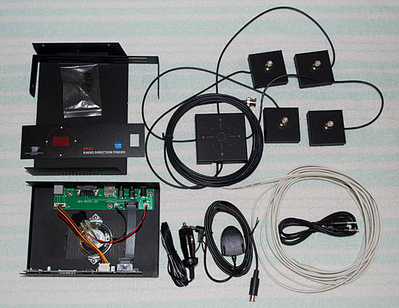
Now a nearly complete version of PicoDopp is available from Global TSCM Group in New York. In the TSCM model DDF2020T, the PicoDopp Processor and MultiDisplay circuits are enclosed in a 7-1/4 x 5 x 2-1/8 inch cabinet for dashboard mounting. Four magnetic-mount antenna bases and a mag-mount antenna switcher unit are included along with data, RF and audio cables. At the TSCM Web site price of $299 (early version without GPS), the DDF2020T costs less than just the PicoDopp processor, antenna and MultiDisplay circuit board set alone.
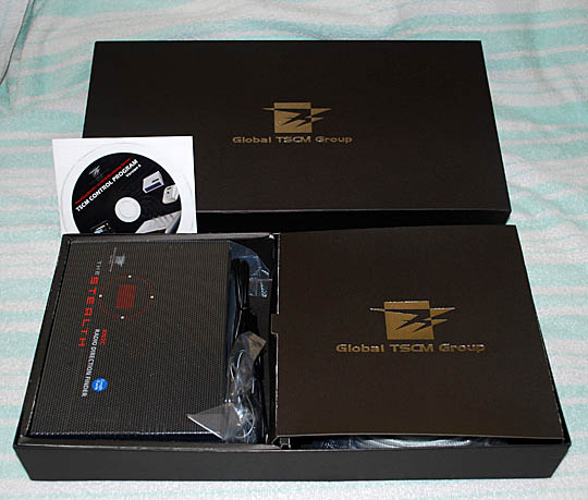
Global TSCM Group calls the DDF2020T a "kit," but it's only about five minutes from being ready to install on the vehicle of your choice, provided that the vehicle of your choice has a ferrous metal roof to hold the mag-mount antenna system parts. Assembly consists of putting the adhesive-backed decal on the front of the display enclosure, snapping the power switch into its rectangular hole and fastening the cover on the box with four screws. After that, all you need to be ready to get bearings are a receiver and four vertical antennas with BNC connectors.
The four antennas can be handi-talkie whips such as the Diamond RH77CA (two meters only), but all four must be identical. Don't mix models, because each model has slightly different phase response. Non-matching whips can cause directional errors. Short identical "rubber duckies" will work, but they will significantly reduce the system sensitivity, making it more difficult to get good bearings on weak signals. Quarter-wavelength whips are ideal. Don't use longer antennas, such as 5/8-wavelength whips, because there will be too much mutual coupling between them. That creates amplitude directivity in the array, which degrades performance in multipath situations.
(It may seem counterintuitive, but for best performance in multipath, a Doppler antenna array should be completely non-directional in amplitude. This is thoroughly explained and illustrated in my Homing In column for the July 2003 issue of 73 Magazine. This article also shows the bad effects of an asymmetrical ground plane.)
My tests were done on two meters with quarter-wavelength whips that I made from 3/32-inch bronze welding rod. They stay in place even at high speeds, which is important. About thirty years ago, I tested a Doppler kit that included whips of thin copper wire. At city driving speeds, the waving array reminded me of a wheat field in the wind. It was no surprise that directional performance under those conditions was very bad. For the same reason, very flexible handi-talkie whips such as Diamond RH519 are not suitable.
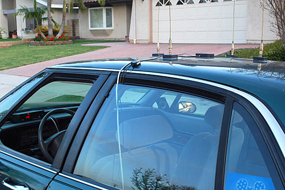
For accurate bearings at every angle around the vehicle, the four antenna bases must be in a perfectly square footprint on the roof. The coax cables from the switcher box are marked NORTH, EAST, SOUTH and WEST. Since the car can be at any orientation, this really means FRONT, RIGHT, REAR and LEFT, as viewed from above. It doesn't matter if you install the whips in this "diamond" pattern or in the traditional "square" pattern (RIGHT FRONT, RIGHT REAR, LEFT REAR, LEFT FRONT). Just make sure that adjacent antennas are equidistant from each other and the corner-to-corner distances are also equidistant. For two meters, a good pattern is 18 inches between adjacent antennas and 25.5 inches corner-to-corner.
There should be at least a quarter-wavelength of metallic ground plane around the base of each antenna. A symmetrical ground plane around the entire array is also important for best results. This means that the array should be mounted in the center of the vehicle roof. Don't put it right in the front or back, to one side, on the hood, or on the trunk lid.
Some of these antenna precautions are in the DDF2020T manual, but not all. The 14-page manual is a bit of a hodge-podge with some paragraphs taken from the PicoDopp Web site, some paragraphs taken from this Homing In Web site, and some paragraphs that are specific to the KN2C packaged system.
The manual states that this set uses the "modified Joe Moell Wideband Antenna design." My technique of putting PIN type diodes at both the common point and the whip base for each of the four antennas has become a standard for hard-switched Doppler sets because it provides wide frequency coverage for the array. Coax lengths from the common point to each whip base are not critical, so long as they are equal. My original circuit required pull-down logic and a +3.7V DC bias supply. Advances in PIN diodes and high-current logic drivers have made it possible to change to pull-up logic and no bias supply -- that's the modification.
My transmitter hunting van is full of RDF gear and has lots of antennas mounted on it, so I convinced April (WA6OPS) to let me test the DDF2020T in her 4-door sedan with her Kenwood TM-732A transceiver. Experience has taught me that Dopplers work best with mobile radios. Many handi-talkies and scanners with "wide open" RF front ends can be desensitized by transients from the antenna switching. The best receivers for Doppler RDF have bandpass filters at the RF input.
Don't transmit through the antenna array. PIN diode switchers are not as fragile as switchers with monolithic preamplifiers, but a few watts of RF could cause failures. If you use a transceiver and can't disable the transmit function, put it on the lowest power setting and disconnect the mike.
The DDF2020T displays shows the bearing in numeric degrees and also on a circular LED ring, called a pelorus display. There are 36 LEDs in the ring. All are red except the top one, which indicates that the signal is dead ahead of the vehicle. It's bright blue so that it stands out, even when you aren't looking directly at the display. Every two seconds, all of the LEDs flash for a few milliseconds to make the relative signal direction easy to discern in the dark. Maximum update rate of the pelorus display is 15 times per second. The numeric display updates three times per second.
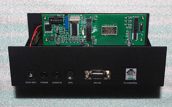
Once the antenna system is in place, it takes just a few minutes to hook up the display unit and antenna connections, audio from the receiver, and power. The speaker inside most radios is silenced when you plug the audio cable into the external speaker jack, but there is a speaker inside the DDF2020 display box. There is also a jack in the rear of the display unit where you can connect your own external speaker.
Before you're ready to go transmitter hunting with DDF2020T, it must be calibrated so that bearings on the LED ring show the correct incoming angles of signals with respect to the vehicle. This is done by adjusting a multi-turn trimpot on the processor board with a small screwdriver through the hole in the top cover. Once calibration is completed, it need not be done again unless the receiver is changed, the frequency band is changed, or the antenna system elements are changed. If you temporarily remove the mag-mounts from the vehicle, you must return them exactly to their previous locations if you want to avoid having to recalibrate.
Adjust the calibration trimpot for the top LED to be on with a dead-ahead signal. You are going to be homing in on hidden transmitters by driving toward them, so you want the most accurate bearings to be ahead of you. The easiest way is to have someone stand directly in front of the vehicle with a transmitting handi-talkie while you adjust the trimpot. However, that's only OK for a preliminary setting. The final calibration should be done with a signal that's at least a block away. You should verify the calibration while you drive toward the signal.
I have two "standard courses" here in Fullerton that I use for calibration and testing of Doppler sets. Both are streets that run radially from a two-meter repeater at an aerospace facility. While the repeater is active, I tune to the output and drive directly toward it to average the local multipath effects. To verify indication of other directions, I drive circles in an open parking lot next to this street. The repeater is line-of-sight from the first test course, but the second has two hills and lots of nearby buildings along the way to provide signal bounces (multipath). I use that course to compare multipath performance between antenna systems and Doppler sets. I often make checks before T-hunts to make sure that calibration is still correct and that the antenna system is working properly.
Once calibrated, bearings are always shown relative to the vehicle's orientation. Vehicle heading from the optional GPS unit can be combined with the vehicle-reference bearing information to give headings with respect to true north, but that is only for computerized mapping and bearing sharing, not for the panel display.
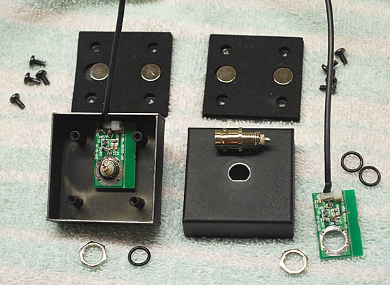
Calibration of the DDF2020T went smoothly and the unit gave correct indications in clear areas, but I was disappointed with its performance on the multipath course. The display was much less steady while driving, compared to the Doppler set in my RDF van. That prompted me to carefully inspect the antenna bases on the DDF2020T. I discovered that the coax shields and the shells of the BNC connectors for the whips were insulated from the magnet covers. In addition, there were thick non-conductive pads under the covers for protection of the vehicle roof. The result of that combination is very little RF coupling between the coax shields and the vehicle ground plane.
The DDF2020T isn't the first Doppler antenna system that I have tested and found to have such poor RF coupling. On this page of the Homing In Web site, I describe why this is undesirable, why it makes bearings unstable while in motion through multipath, and how this problem was corrected in another commercial Doppler model. I decided to see if the DDF2020T could be improved in the same way.
It took less than an hour to modify all of the whip bases, following the procedure at the bottom of the page. I also made "coasters" to go between each whip base and the roof, held in place by the magnets. Each coaster is a sandwich of a 2-1/4 x 2-1/4 inch piece of aluminum foil on top of 2-1/2 x 2-1/2 inch piece of parchment paper. This sandwich formes a flat-plate capacitor with the foil and the vehicle roof as plates of the capacitor and the parchment paper as dielectric. It provides excellent RF coupling to the vehicle roof.
I used Reynolds Parchment Paper from the supermarket baking supplies aisle for this experiment. For a permanent fix, one could solder a thin non-ferrous cover over the base in place of the aluminum foil and cover that with polyester film instead of the parchment paper for rooftop protection.
The modification made a noticeable improvement in the steadiness of the display as I drove the multipath test course. Since it provided a much better counterpoise for each whip antenna, I think it also improved the overall sensitivity of the system, giving better bearings on weak signals.
The switcher unit is designed to operate from 100 to 1000 MHz. Information about using the DDF2020T for RDF on bands other than two meters is in the manual. Because of the importance of having at least a quarter-wavelength of ground plane under and around each whip, the practical lower frequency limit for optimum results on a standard passenger car is about 140 MHz.
The manual doesn't mention it, but Doppler sets can track VHF/UHF AM, analog TV and other carrier-mode signals in addition to voice and digital FM. However, the receiver must always be in the FM mode. Dopplers are not suitable for tracking non-carrier signals including SSB, broadband noise, and short pulses such as 60 Hz power-line arcing.
PicoDopp is an excellent RDF system and Global TSCM Group has done an impressive job of packaging it to create the most inexpensive complete Doppler RDF product with serial interface now in production. After the antenna base modifications, I found its performance to be on par with Doppler sets costing much more. A rewrite of the manual would make it even better.
In addition to the DDF2020T, Global TSCM Group also offers the DDF2020M, a one-piece Doppler set with a miniaturized antenna set built into the display unit enclosure. This antenna has very close whip spacing and a very small ground plane underneath (9-1/2-inches diameter), so it is not suitable for mobile use on VHF bands. See update at the top of this page.
Provided with the DDF2020T is a CD with Navi 2020 software that accepts bearings in serial format and plots them on Google Earth maps. It is a licensed version of the WB6EYV's GoogleHunt program that I described in the Winter 2012 Homing In column. A matching miniature roof-mount GPS receiver is available from Global TSCM Group to complete this standalone computerized RDF package.
2. Remove the four screws and the bottom cover with magnets from one whip base.
3. Unsolder the bare wire jumper that goes from the circuit board to the center pin of the BNC receptacle at the connector end only.
4. Remove the nut from the BNC connector and push the connector out the top. Be very careful not to damage the components on the circuit board while doing this. Then pull the little circuit board and coax out of the whip base.
5. Lightly sandpaper the paint from the top edge of the BNC connector hole and sandpaper the paint from the bottom edges of the base enclosure.
6. Install the BNC connector back into the enclosure without the O-ring on the top, but with the O-ring on the underside to space the board away from the enclosure.
7. Reinstall the circuit board and tighten the nut on the BNC connector. Solder the jumper wire back onto the BNC center pin. Make sure that the jumper isn't shorted by contacting the nut. You should now have conductivity between the BNC shell and the bottom edges of the base enclosure.
8. Replace the enclosure bottom and magnets and secure with four screws.
9. Repeat for the other three whip bases, then reconnect the antenna coax and data cables.
Caution: The Global TSCM Group warranty does not cover "alterations outside our facilities," so this modification must be made at your own risk.
© 2012 Joseph D. Moell. All rights reserved.
 Back to the Homing In home page
This page updated 23 March 2024