Excerpts from
APRS Puts Doppler Headings On The Map
Homing In, 73 Magazine, August 1995
by Joe Moell KØOV
Retire Your Protractor
Wouldn't it be great if your doppler indications could be displayed
directly on a road map? While we're at it, why not have bearings from
other base and mobile stations appear on the same map, so you can see
instantly where they intersect? Automatic Packet Reporting System (APRS),
a shareware computer program, makes all this possible right now.
When Bob Bruninga WB4APR first developed APRS, it was just for mapping
packet stations, both fixed and moving, for fun and public service. He
envisioned it as a way for officials at events such as marathons and boat
regattas to instantly spot the locations of contestants, VIPs, ambulances,
and so on. Then he began to add features such as dead reckoning of moving
objects, messaging between unconnected stations, and grid-square plotting.
With the latest version, storm tracking nets can pinpoint their weather
spotting units, HF contesters can display Packet Cluster DX reports, and
transmitter hunters can create multi-station RDF networks to quickly zero
in on jammers, stuck transmitters, and stations in distress.
Since APRS DOS version 3.0, the program has included
a steadily improving suite of RDF features. The most advanced of these are
the doppler inputs, which became fully operational in DOS version 5.03a. Bob
added routines to accept and display bearings from Doppler Systems RDF
models having 300 bps RS232 output. For Doppler Systems models without
serial data output and for other brands of dopplers, WB4APR collaborated
with Robert Swain N7LUE to develop a universal interface.
Inside the Interface
 In all of the popular doppler designs in the ham market, the 360-degree
azimuth circle is represented by 8, 16, or 32 LEDs. Somewhere in the
control/display electronics, 4-bit parallel data representing antenna
position and a direction pulse to latch this data for the display are
available. The block diagram shows how N7LUE's interface converts this parallel
data to a serial output. All signals are tapped from the doppler circuits;
normal operation of its LED display is unaffected.
In all of the popular doppler designs in the ham market, the 360-degree
azimuth circle is represented by 8, 16, or 32 LEDs. Somewhere in the
control/display electronics, 4-bit parallel data representing antenna
position and a direction pulse to latch this data for the display are
available. The block diagram shows how N7LUE's interface converts this parallel
data to a serial output. All signals are tapped from the doppler circuits;
normal operation of its LED display is unaffected.
U1 is a 74HC75 4-bit latch. It is disabled when the circuit is used with
Doppler Systems, Dick Smith, and other designs that have latched 4-bit
direction data available. Other dopplers such as the 16-LED KØOV/WB6UZZ
Roanoke Doppler and the WA4BVY DoppleScAnt use a 4514 or 4515 latching
4-to-16 decoder IC, which does not put latched 4-bit direction data onto
external pins. Data is latched by U1 for these models.
Latched data from U1 goes to U2, a Microchip AY31015D universal synchronous
receiver/transmitter (UART) that performs the parallel-to-serial
conversion. The output of U2 is a stream of 8-bit ASCII characters from
"@" (01000000) to "O" (01001111), representing the 16 possible states of
the 4-bit input data.
Note that no matter how many LEDs or vertical antennas your doppler has,
N7LUE's board always outputs 16 output characters, representing 22.5 degree
azimuth increments. U4 converts the serial data from 5-volt logic level to
RS232 standards.
APRS software can process about eight bearing samples per second. U5 is a
4024 binary countdown, driven by the doppler's antenna rotation clock
oscillator. Its 8 Hz output sets the UART character output rate. Q1, Q2,
and U7 sense receiver audio, preventing random data output when no signal
is being received.
U8 was added to the design for situations where APRS is transmitting packet
bearings in the same band that the doppler is monitoring. When the packet
TNC is keyed down, the doppler bearing will probably be erroneous. The U8
data mute interrupts serial output during packet transmissions, to prevent
these bad bearings from being processed by APRS.
Crunching the Bearings
WB4APR's software accumulates and calculates the average and standard
deviation of a series of bearing samples to the nearest degree. It plots
the average as a yellow vector on the screen map. The standard deviation
calculation gives a measure of the quality of the bearing data. When
samples differ greatly in direction over a short time, deviation is large
and the displayed line is dotted to indicate a low quality bearing. The
more breaks in the line, the larger the deviation is. When doppler
indications are steady, deviation is low and the yellow line is solid. A
violet rectangle at the top of the APRS map display provides additional
bearing quality data.
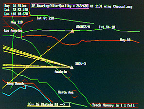 The photo shows typical APRS doppler data displayed on a base station PC
screen. The dashed yellow bearing lines from the KØOV icon were picked up
during a 30 second transmission from a mobile station. The cross-bearing
from WB6UZZ/M could have been received and plotted by packet or entered
manually by the APRS operator from a radio report.
The photo shows typical APRS doppler data displayed on a base station PC
screen. The dashed yellow bearing lines from the KØOV icon were picked up
during a 30 second transmission from a mobile station. The cross-bearing
from WB6UZZ/M could have been received and plotted by packet or entered
manually by the APRS operator from a radio report.
The APRS cursor has been moved manually to the intersection of the KØOV and
WB6UZZ bearings. The exact latitude and longitude of this intersection is
displayed in a box at the upper left corner of the screen. If the bearings
are good, that is where the transmitter is. Even if the APRS map has errors
in the location of roads and towns, the coordinates obtained by
triangulation are correct if the coordinates of the RDF stations have been
correctly entered.
Now that the APRS base station has coordinates of the unknown signal, its
operator can notify mobile transmitter hunters. Better yet, the base
station can automatically transmit a stream of packet transmissions with
bearing data to a group of mobile transmitter hunters running APRS and
their own dopplers. The mobiles must input their location and vehicle
heading to APRS for bearings to be plotted. Although this can be done
manually, the best way is with the NMEA-0183 output of a Global
Positioning System (GPS) receiver.
Since most laptop PCs have only one or two serial ports, hooking up three
peripherals (TNC, GPS and doppler) poses a major roadblock. WB4APR has
created a Hardware Single Port (HSP) mode to permit GPS and TNC to share
one port. You will need to build a two-transistor data switch, activated
by the Data Terminal Ready (DTR) line on the serial port. Details and
circuits are in the README.GPS file in APRS documentation.
To work with the serial RDF interface, your copy of APRS must be
registered with a DF validation, which costs an extra nine dollars over the
regular APRS registration fee. However, there are other ways to get RDF
information into the APRS screen without special registration. Any base or
mobile station running APRS can manually put its RDF bearing into its
station position report to be transmitted on packet. An APRS operator can
also get RDF bearings and positions of other base and mobile stations via
voice radio, then enter and transmit them on packet from his station.
Packet stations not running APRS can put their RDF bearings in their beacon
texts. If formatted properly, APRS-equipped stations receiving the beacons
will automatically receive and display the bearing lines. The APRS
README.DF file gives detailed explanations of how to do all this.
The README.DF file also describes how to set up remote unattended RDF
stations consisting of a receiver, doppler, serial interface and packet
TNC. No computer is needed if the TNC is set up to properly format and
beacon the RDF data. Three of these stations at good receiving sites
around a city could give any APRS station in the area instant triangulation
data whenever an unknown signal comes on the air.
Get In On The Ground Floor
APRS and its interface to dopplers and GPS are not a "plug and play" system
yet. The hardware and software are constantly evolving in response to user
feedback. Every ham's APRS installation will have unique challenges due to
differences in computers, dopplers, TNCs, and GPS receivers. There are
important control and local QRM issues involved in setting up remote RDF
sites. Your experiences and suggestions are needed to optimize the bearing
averaging algorithms.
There is no way that Homing In can cover all the nuances of setting up
APRS RDF networking. You will need to read the voluminous APRS documentation
and plan your installation carefully. This effort will pay off in your
being the "first on your block" to use with a revolutionary RDF technique
that may someday become a commonplace way for hams to perform public
service and self-policing.
© 1995 Joseph D. Moell. All rights reserved.
 Back to the Doppler-to-RS232 Front Page
Back to the Homing In home page
This page updated 20 December 1997