 Parts list of the offset attenuator
The fox's signal at the start of an on-foot transmitter hunt may tickle your receiver with only a fraction of a microvolt. But when you get in close, it could get pounded with nearly a volt of RF, even if the transmitter is running low power. The S-meter circuit of a typical VHF-FM rig won't help you get bearings at that level. It probably shows full scale at 10 microvolts, giving only about 30 dB range from minimum to maximum. Limited range is good because it's easy to see the meter peaks when you swing a directional antenna, but it's bad because your meter will stay pinned when the signal is strong.
An RF attenuator is a device that goes between antenna and receiver to reduce the signal strength down to within the range that the receiver S-meter can handle. Without one, you may think you're close to the fox when you're still far away. You won't be able to get close enough to a camouflaged hidden T to identify it. The amount of attenuation should be adjustable so that you can add just a little when your S-meter first pins, up to a lot as you get within a few feet. Special ARDF receivers used by champion foxhunters have electronic attenuation built in, but ordinary handi-talkies don't. Adding it would require major micro-surgery in the HT.
To Solve Leakage, QSY
External resistive (sometimes called "passive") attenuators are popular for mobile T-hunts. They have several shielded sections, each with resistors to soak up the RF signal and a switch to put the section into and out of the line. But they are not the answer for on-foot hunts, because handi-talkies and scanners are notorious for poor case shielding. A passive attenuator cuts down the RF voltage into the antenna jack, but strong signals will still penetrate the case and pin the S-meter.
A better way to get bearings on nearby foxes with HTs is to convert the strong on-frequency signal into a weaker off-frequency signal. Then tune your receiver to the offset signal and measure its strength versus direction, either with a dedicated RDF antenna or the "body shield" maneuver.
When this type of device was originally described in the early 1990s by Anjo Eenhoorn PAØZR, it was called an active attenuator. Since there are other kinds of attenuators that are also called "active," I prefer to call it an offset attenuator. That term describes how it solves case leakage by offsetting the signal frequency. An offset attenuator consists of a local oscillator (LO) connected to a diode mixer through the attenuation control. The higher the LO level, the higher the amplitude of the offset signal applied to the receiver. To increase attenuation, decrease the LO signal into the mixer with the control.
The offset attenuator described here is so easy to make that it's a good project for every member of your club, especially if experienced builders help out the first-timers. When I first published it, all parts were at local Radio Shack stores, so I included RS part numbers in the parts list. Sadly, very few RS parts stores exist now and many other local electronics parts stores have closed or ceased sales to the general public. If one still exists in your area (such as Marvac Electronics here in southern California), please give it your business. Otherwise, you should be able to find all parts (except perhaps the crystal clock oscillator) by mail order from companies such as Mouser Electronics, Jameco Electronics and DigiKey. Look for leaded components unless you enjoy working with surface-mount devices. The Updates section below has suggestons for suitable clock oscillators.
Parts list of the offset attenuator
C1,2   470 pF ceramic disc
C3     .0047 µF ceramic disc
R1,2   2.2K 1/4 watt
R3     4.7K 1/4 watt
D1     1N4148 signal diode
J1     UG-1094 BNC socket
VR1    5K audio taper potentiometer
S1     Toggle switch
U1     7805 regulator (+5V)
X1     4.0 MHz clock oscillator
       Battery connector
       Knob
       BNC cable
       AWG 24 bare wire
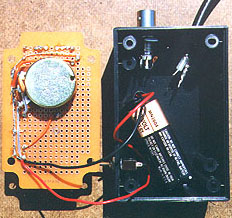
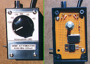
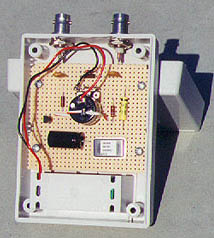
Nowadays, hams expect a special circuit board for every ham construction project. Not this one. There is so little wiring that it simply isn't necessary. A universal project board works just fine. I found a 2 X 3-1/4 X 1-3/8 inch plastic box with an aluminum cover and a predrilled 1-7/8 X 3 inch project board mounted inside. J1 is a BNC connector to mate with the cable from your RDF antenna. The output cable has a BNC plug to match the antenna connector of many hand-helds. If your antenna or radio uses different connectors, make changes accordingly.
S1 is a subminiature toggle switch. It's easy to accidentally bump it to the ON position when you toss the unit into the back seat after the hunt. If you are good at making square holes, you can replace S1 with a slide switch to minimize the chance of accidentally run-down batteries. If you don't have a stock of quarter-watt resistors in your junkbox, buy the five-pack of 2.2 K resistors. For R3, use two of the 2.2 K resistors connected in series.
 Step by Step Construction
Cut the shaft of potentiometer VR1 to 5/8 inch, as measured from the outside end of the bushing. Drill a 5-16-inch hole, one inch from the top edge of the circuit board, centered between left and right edges. Drill holes in the box for the coax receptacle (J1) and the RG-58 output cable (a BNC jumper cable with one connector cut off). Drill a hole for power switch S1 in the lower left side such that there is plenty of room for the battery and VR1 when everything is assembled. Mount VR1, J1 and S1, oriented as shown. The copper etch on the circuit board goes on the same side as the body of the potentiometer, toward the interior of the box.
Strip the center conductor and braid of the output cable as shown. Solder a one-inch bare wire to the ground lug of J1 and connect one end of C1 to the center pin of J1. Extend the bare wire and unconnected end of C1 upward, to be connected later.
Mount U1, X1, D1, C2 and the three resistors on top (no copper) side of the board with the leads extending through holes to the copper etch side. Install two terminal pins (RS 276-1987) on the input (signal and ground) for later connection to J1, and two pins on the output side for the wiring to P1. Wire the pins and all the parts on the board per the schematic diagram. Tie the "RF ground" (rake symbol) nodes together with bare wire.
Install C3 on the rear of the board from the clockwise lug of VR1 to the crystal oscillator output. Use insulated wire for jumpers and the regulator output.
I used a "full can" crystal oscillator, which is designed to fit into the socket for a 14-pin dual-inline packaged (DIP) integrated circuit (IC). One corner is squared instead of rounded, corresponding to the location of pin 1, which has no internal connection. There is also a marked dot on top of the cover at this location. Counting clockwise from that pin as viewed from the bottom side of the oscillator, the next pin (7) is ground, next (8) is the output, and next (14) is supply +5 volts. There are also "half can" oscillators which fit into the socket for an 8-pin DIP IC." In that case, pin 1 is the dot, not connected. Power goes to pin 8, ground to pin 4 and output is pin 5. See the Updates section below for some possible sources.
Wire the battery connector and S1 into the circuit. If you have a voltmeter, turn on S1 and check for +5 volts at the regulator output pin. If you have an oscilloscope, verify 5 volt peak-to-peak square wave at the oscillator output pin. Both are measured with respect to the negative battery terminal. Turn off S1 when you are finished.
Now it's time to put it all together. Solder the center conductor and shield of the output cable to the output terminal pins on the etch side of the board. Put the board in the box, extending the leads from J1 through holes on the top left. With the board mounted in place with two supplied screws, tack-solder the J1 leads to the input terminals. Drill a 5/16-inch hole in the aluminum box cover, 1-1/16 inch from the top, centered between left and right, to clear the shaft of VR1. Make cover labels using your favorite technique, then install the cover and knob.
 Antidote For Overload
Using an offset attenuator for on-foot foxhunting is easy and efficient, once you get the hang of it. An S-meter on your receiver is a big help in getting RDF bearings with this attenuator and a small beam or quad, but it is not mandatory. You can open the squelch and use the quieting property of FM signals to get a good idea of signal direction.
At first, get bearings on the fox's frequency with S1 turned on. Start with the dial full clockwise, which is minimum attenuation (about 4 dB). Increase attenuation as necessary by turning the knob counterclockwise. When it reaches the stop, you have attenuated the signal about 20 dB.
When this isn't enough attenuation, tune your receiver up or down to the first offset frequency. (Examples: 146.565 + 4.0 = 150.565 or 146.565 - 4.0 = 142.565) Return VR1 to full clockwise, which is the equivalent of about -30 dB, and continue the hunt, increasing attenuation as you approach. By the time you reach 100 dB, you should be within a few feet of the signal source, depending on its power and antenna configuration. Considerably more than 100 dB effective attenuation can be achieved with this unit, but that was the limit of the calibrating I could do with my milliwatt VHF signal generator.
This offset attenuator can be used with any VHF transceiver or scanner radio that has a removable antenna. Provisions for attaching to sets with integral antennas (such as the Alinco DJ-C1T and DJ-S11T) are not included. The receiver must have sufficient frequency coverage to permit tuning it 4 MHz away from the hunt frequency. If your hand-held does not have an extended range receiver (the Radio Shack HTX-202 is an example), substitute a 2 MHz oscillator. To save time while transmitter hunting, program both the transmitter frequency and the offset frequency into receiveer memories so you can switch back and forth quickly.
Current drain of typical oscillators with TTL circuitry is over 20 mA, so maximum battery life with them will be about 15 hours. Look for a CMOS oscillator that has much lower current drain. Another way to improve battery life is to replace U1 with a "low dropout" regulator such as the LM2931A2-5.0. This makes it possible to use 9-volt batteries down to about 5.5 volts instead of 7.5 volts.
There are two popular types of rotary potentiometers, linear taper and audio taper. Audio taper is best for VR1 because it spreads out the high attenuation values on the dial when you wire it so that high attenuation is on the counterclockwise end, like a volume control. If your unit works on the opposite fashion and the attenuation is abrupt, simply swap the wires on the two outside terminals of the potentiometer.
Offset attenuator operation may be degraded when receiving frequencies that are an exact multiple of the oscillator, such as 144.0 and 148.0 MHz. If there is a strong communication or paging transmitter that offsets onto the frequency you are monitoring, you may experience cross-modulation interference. An example would be QRM from NOAA weather radio on 162.55 MHz when you are hunting a 146.55 MHz signal by listening on 150.55 MHz. This effect is worse with odd multiples of the oscillator frequency and oscillators below 4 MHz.
In the unlikely event that you cannot adequately attenuate the hidden signal with the receiver tuned one offset above or below the transmitter frequency, try doubling or even tripling the offset. (Example: For a 4 MHz oscillator unit, tune 8 MHz or 12 MHz above or below the receive frequency.)
Avoid transmitting through this attenuator. Your antenna will emit strong spurious signals and you may burn out D1. Set the power output down to the lowest possible level on your hand-held. Fortunately, if you forget and cause a failure, repairs are easy and inexpensive.
There is no isolation between the mixing diode and your antenna. Offset signals not only go into your receiver, but they also go back to your RDF antenna, where they are radiated. This may cause cross-modulation QRM to nearby receivers, even outside the ham bands, when you are very close to the fox antenna.
Remember that an offset attenuator does not greatly reduce the level of on-frequency signal into your radio, so it does not provide protection for your receiver's front end. If you touch your RDF antenna to the antenna of a powerful fox transmitter, you may damage both the receiver and the offset attenuator.
At right: NASA Pre-college Science Academy students at Pasadena City College in California built twenty attenuators and steel-tape yagis during Saturday-morning sessions for their Spring 2001 radio-orienteering project. Phil Barnes-Roberts AD6PQ modified the KØOV offset attenuator layout to fit into a larger box with integral battery holder for ease of construction by the students. Attenuators were mounted to booms of the yagis with plastic pipe clamps. The story of this exciting youth program was in my Homing In magazine column for August 2001.
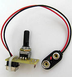
Marvin Johnston KE6HTS offers a "semi-kit" for this attenuator (at left below). The circuit board is 3/4 inch by 1-1/4 inches with surface-mount components already installed. You solder on the battery leads, antenna leads, and mount it into your enclosure with connectors suitable for your radio and RDF antenna. You can mount the potentionmeter directly to the board or use extension wires to mount it on your case. Choose 2 MHz or 4 MHz for the CMOS oscillator. Bare circuit boards are also available. Contact Marvin by e-mail for more information and prices.
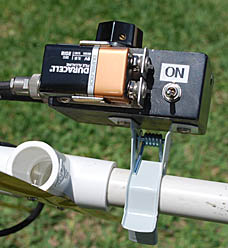
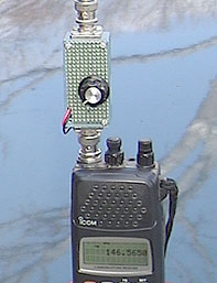
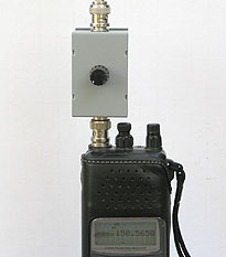
With Marvin's circuit board, you can make a miniature offset attenuator that attaches to the antenna jack on your hand-held receiver. I built the one at right below in a Pomona Electronics #2391 shielded box, which comes with BNC connectors installed. My battery holder is outside on the rear for easy access. I didn't bother with an on-off switch -- I just remove the battery when not foxhunting.
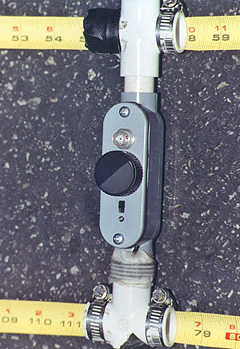
Marvin Johnston also offers the attenuator circuit board mounted inside the boom of a WB2HOL-style measuring-tape beam. Actually, the circuit is inside a plastic pass-through electrical box (with waterproof gasket) that is incorporated into the PVC pipe boom. While holding the mast of the beam, you can adjust the attenuator with the thumb of the same hand.
A complete offset attenuator with enclosure and connectors, ready to use, is available from Arrow Antennas, shown below. It uses a miniature coin-cell lithium battery. A product review is in my Winter 2006 Homing In column for CQ-VHF Magazine.
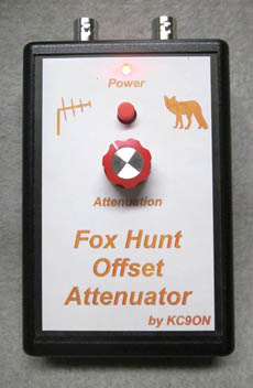
John Clements KC9ON sells offset attenuators in several forms, including kits, populated SMD circuit boards and assembled/tested units in a case, as shown below. His company is 3rd Planet Solar.
(My usual disclaimer applies -- the above suppliers are solely responsible for their products.)
Text and artwork © 1998-2025 by Joseph D. Moell. All Rights Reserved
This page updated 10 July 2025
Receiver Compatibility
When tracking higher power fox transmitters, these effects occur at greater distances. Tests were preformed with the Baofeng Model UV-5R, which is typical of all Baofeng hand-held sets.
Updates
 After using this attenuator for several years, loaning it to many newcomers at ARDF practice sessions, and communicating with others who have built them, I have some additional comments and suggestions:
User Feedback
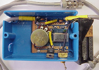
 At left: The photo by Wayne Yoshida KH6WZ shows how he built his unit into a plastic electrical box, which he found for less than a dollar at a hardware store. SuperStrong Adhesive from 3M (not shown in the photo) holds the coax in place and provides strain relief. The potentiometer holds his circuit board against the front panel. Flanges on the box matched the mounting holes on the Arrow yagi he used at first. Later he decided it was better to fasten the attenuator to his body when hunting, so he cut off the flanges and attached an aftermarket belt clip designed for Nokia wireless phones. The clip is designed to allow the phone to swivel on the clip or be removed by pressing a release lever. Wayne used a crystal oscillator from Teknopak for X1 and NTE replacement semiconductors for D1 (NTE519) and U1 (NTE960).
Kits and Assembled Units

 Back to the Homing In home page